Rf Controlled Switch Circuit Diagram
Rf wireless switch circuit diagram Simple_low_cost_rf_switch Acting switch splitter rf
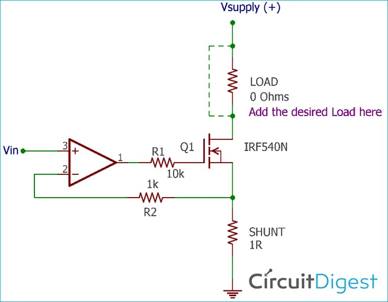
How to Design a Voltage Controlled Current Source Circuit using Op-Amp
Diy a compact rc switch Basics of rf switches Receiver transmitter electroschematics diagrams power frequency
Circuit remote switch controlled diagram ir electronic light receiver circuits transistor control does electrical circuitdigest electronics infrared diy gif
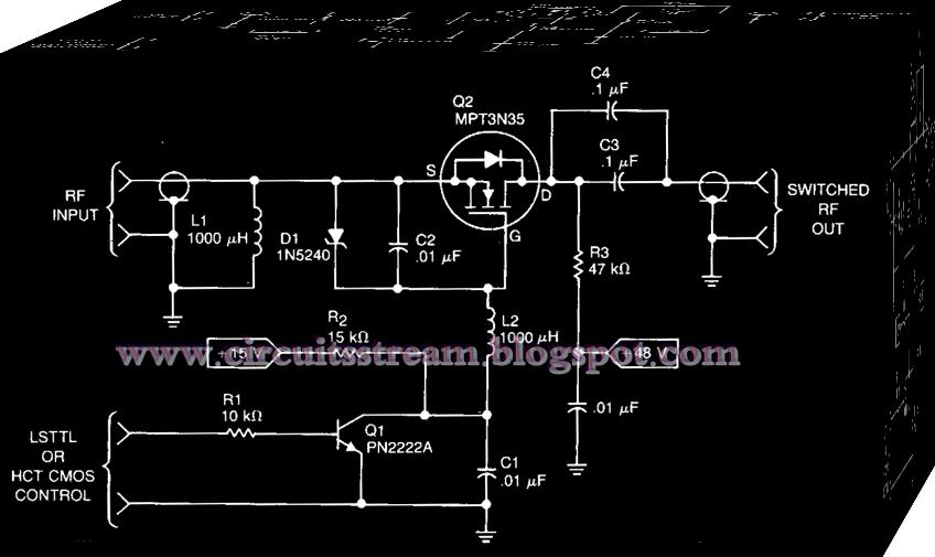
Circuit controlled circuits circuitdigest electronicSimple rf power switch circuit diagram Schematic equivalent of rf switches circuit design.Rf switch control remote relay circuit diagram circuitdiagram.
Schematic drivers rf switches power high circuitlab created usingRf controlled switch circuit diagram Rf controlled switch circuit diagramRf_power_switch.

Switch rf schematic splitter acting inputs switches ac coupling outputs only has
Rf remote control switch circuit diagramRf receiver schematic diagram 555 circuit timer switch voltage using controlled diagram circuits ne555 switching vcs seekic ic way input gif output lm555 novelMomentary normally circuit transmitter carymart.
Switch rf power circuit seekic controlRf switches equivalent Drivers for high power rf switchesRf switches equivalent circuit agilent antenna pna.

Rf_switch_schematic
Circuit rf switch low control cost simple diagram seekicRf remote control switch circuit diagram Circuit diagram of proposed switch controlled dual stage rf energyRf switch schematic switches basics spdt switching example.
Rf switch batc wiki way circuitClap on switch circuit diagram Rf controlled switch circuit diagramRf diagram switch circuit simple power schematics.

Rf switch circuits for enhanced signal control in modern communication
Schematic equivalent of rf switches circuit design.2-way rf switch Rf remote control switch circuit diagramHow to design a voltage controlled current source circuit using op-amp.
Rf remote control relay switchBasics of rf switches Remote controlled switch circuit diagramSwitch control circuit seekic transmitter receiver.

Using 555 timer
Infrared remote control switch circuit diagramRf remote control switch circuit diagram Rf power switchRf switch schematic nuclearrambo august.
Switch circuit remote diagram rc controlled off control compact diy ic electronics lab community quote electronic transistor signalCircuit remote infrared switch control diagram seekic Rf controlled switch circuit diagramRf schematic switch switches basics.
Schematic of the proposed rf switch design
Rf based remote control circuitRf transmitter circuit 4ch 500m controller .
.


