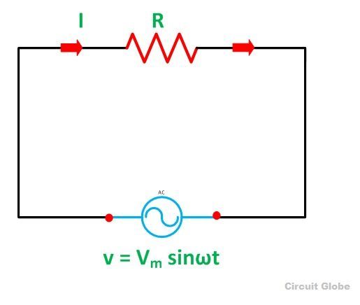
Purely Resistive Circuit Diagram
Power unity circuit factor pure resistive advantages current resistor alternating ac when both Purely resistive, purely inductive and purely capacitive circuits for jee Purely resistive circuit
What is a Pure Resistive Circuit? - Phasor Diagram and Waveform
Power ac circuit resistive purely circuits reactive electrical Resistive circuit ac waveforms current What is a purely resistive circuit? circuit diagram, phasor diagram
What is a pure resistive circuit?
Circuit resistive purely shown solved p2 fig transcribed problem text been show hasCapacitive inductive resistive reactance circuit phasor diagram purely formula definition electrical figure voltage current applied What is purely resistive electric circuitPurely capacitive circuit phasor diagram.
Pure inductive circuit phasor diagramResistive circuit pure ac current diagram resistor phasor instantaneous through value will Unity power factor causes, advantages, improvementsPassive components in ac circuits with equations.

Pure resistive circuit ac purely waveform power instantaneous resistor voltage phasor current supply shown figure
Power in resistive and reactive ac circuitsPurely resistive ac circuit Purely resistive circuit diagramSolved in the purely resistive circuit shown in fig. p2.6,.
Ac supply to pure resistor (theory, phasor & waveformsPhasor diagram of purely resistive circuit What is a pure resistive circuit?Purely resistive, purely inductive and purely capacitive circuits for jee.

What is power factor?
Pure resistive circuit calculation purely phasor resistor supply ac powerAc circuits with resistors, inductors and capacitors Reactive apparent activeWhat is a purely resistive circuit? circuit diagram, phasor diagram.
Ac resistive circuitPhasor diagrams for analysis of ac circuits Active, reactive & apparent powerPower in ac circuits and reactive power.
For a purely inductive ac circuit show that the current lags the
Resistive circuit pure power average instantaneous ac consumed phasor diagramPurely resistive, purely inductive and purely capacitive circuits for jee Resistive current circuit power ac reactive voltage phase circuits factorResistive circuit pure waveform diagram phasor power phase current voltage resistor load ac dryer hair inductive form circuitglobe electrical loads.
Circuit resistive pure figure ac circuits passive equations gif fig electricalacademia electrical findPurely resistive voltage factor Purely resistive circuit diagramWhat is a pure resistive circuit?.

What is a pure resistive circuit?
Circuit resistive pure power ac zero valve phasor diagramCircuit resistive purely Resistive purely resistors circuitsAc supply to pure resistor (theory, phasor & waveforms.
Resistive load power factor purely explainedPurely resistive circuit Purely resistive circuitPurely capacitive circuit phasor diagram.

Power factor explained
Inductive and capacitive reactance .
.


